- Innovation
- CAE simulation
CAE simulation
Computer Aided Engineering
The CAE (Computer Aided Engineering) process at Dinex are a combination of making an 1D system simulation of the emission performance, system design and a system performance evaluation.
The system layout is evaluated using a 1D tool. The system is designed using a CAD (computer aided design) tool, and the system performance is evaluated using FEA (finite element analysis) NVH (noise, vibration and harshness) and CFD (computational fluid dynamics) tools.

Computer Aided Design – CAD
The design is created using the 3D CAD tool SolidWorks which enables the designers to make 3D models of parts and complete system assemblies. The input to the design from customer’s side are:
Requirements
- Performance, durability, materials, serviceability etc.
Vehicle information
- Layout, space envelope, parts attached, road load data, engine & emission data
Dosing & substrates
- Injector details, requirement to substrates sizes/coating
The output from the design phase are:
- A-sample flexible concept emission testing
- B-sample on prototype tooling for DV testing
- C- & D-samples on serial tooling for PV tests
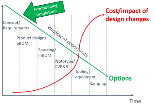
Simulation Driven Product Development
Frontloading simulations to improve product performance & durability already in the design phase.
Finite Element Analysis - FEA
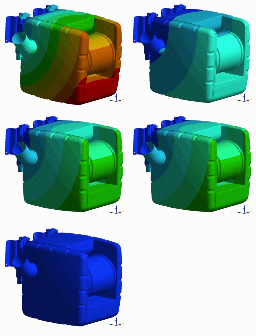
The structural strength, thermal and vibration performance, along with fatigue and life time prediction of the exhaust after treatment system is evaluated using Ansys Mechanical. Ansys is a 3D FEM based tool, where inputs are material fatigue data and customer vibration load data.
Main outputs from the FEA simulation are
- Stress level & displacement amplitudes
- Natural frequencies and mode shapes
- Life time and fatigue prediction
The FEA simulations are validated with the vibration test & surface temperature tests.
Noise, Vibration & Harshness - NVH
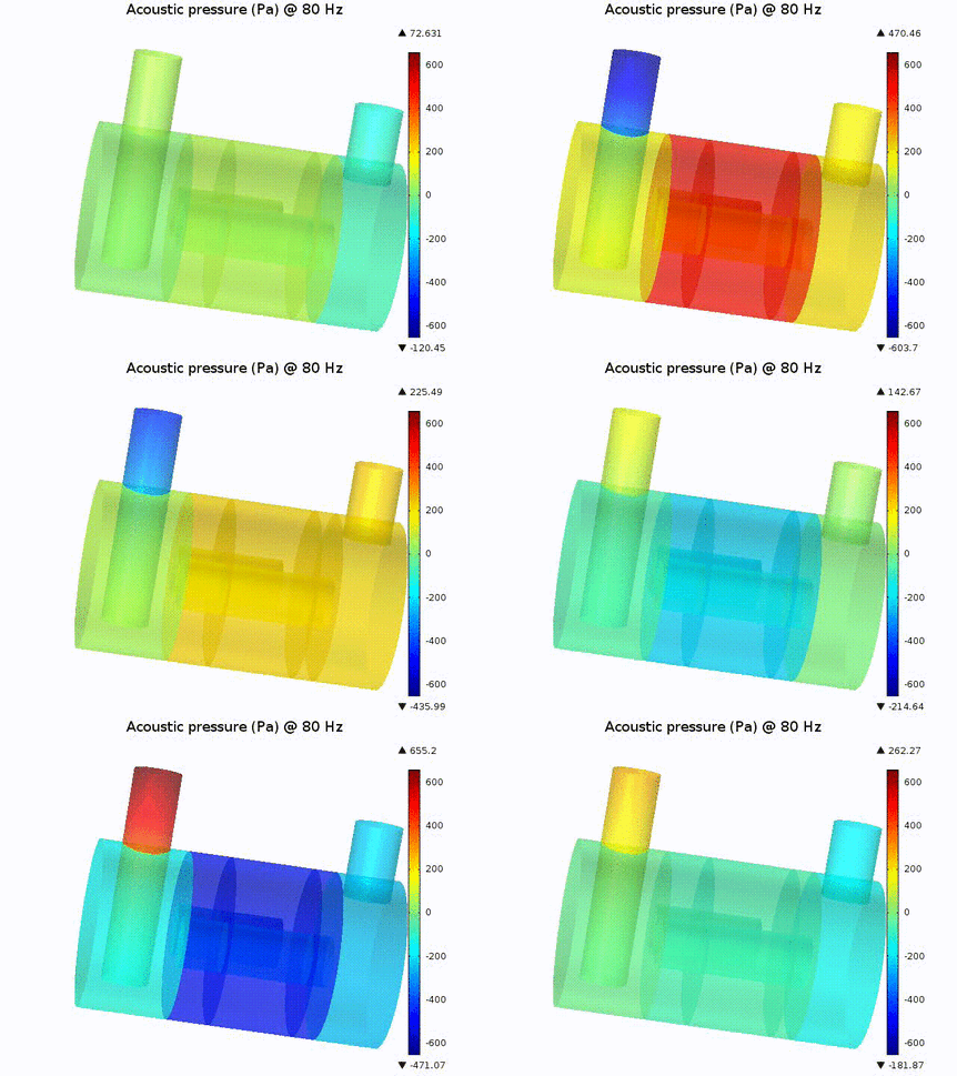
The acoustic performance of the exhaust after treatment is evaluated using Comsol Multiphysics. Comsol is a 3D FEM tool with linear pressure acoustic capabilities.
Main outputs are:
- Transfer matrix
- Transmission loss
The NVH simulations are validated with the flow acoustic test rig.
Exhaust After treatment simulation – 1D CFD
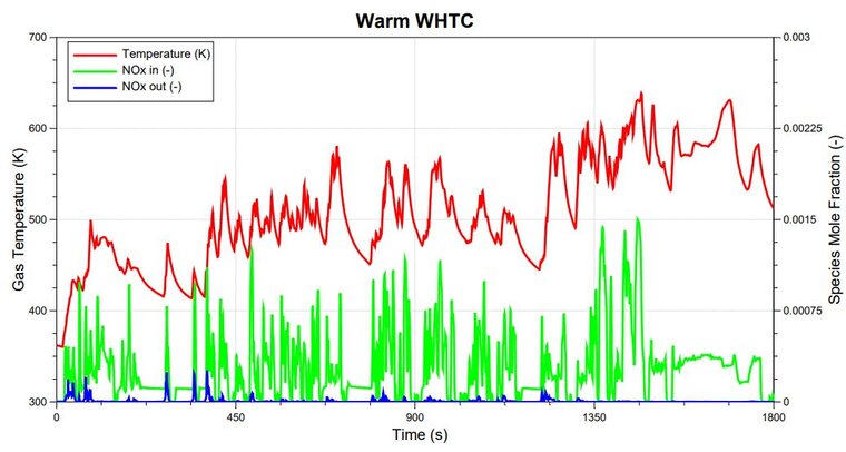
The fluid dynamic & emission performance of the complete exhaust system is evaluated using AVL Boost which has special capabilities within engine and after treatment systems. AVL Boost is a 1D CFD & reaction kinetics tool.
Main output from the simulations are:
- Heat-up time
- Tail pipe NOx emissions
- DOC & SCR Light off
The 1D simulations are validated with SGB & engine dyno tests.
Computational Fluid Dynamics - CFD
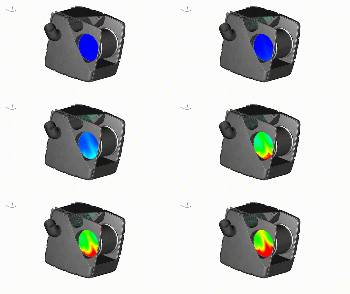
The fluid dynamic performance of the complete exhaust system is evaluated using AVL Fire which has special capabilities within engine and aftertreatment systems.
Main output from the 3D CFD simulations are:
- Flow uniformity index & Flow distribution
- Backpressure
- Heat loss and surface temperature
- Ammonia (NH3) uniformity index

The A-sample phase is driven bt CFD multiphase simulations to predict the right uniformity, backpressure and deposit risk.
The CFD simulations are validated with engine dyno tests.
